by Thomas O’Neil for the University of Virginia Physics Department posted with Tom’s permission.
Home Lab 14 Alternating Current
Overview
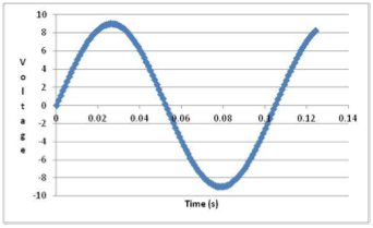
Alternating current changes the applied voltage in a sinusoidal fashion. For a 9-Volt 60
Hz alternating current, the frequency is 60 Hz so the period is 1/60 (0.0167) second.
The amplitude of the voltage swings from +9.0 volts to -9.0 volts and back in one cycle as shown in the diagram to the above.
As shown in the Faraday experiment a changing electric field produces a changing magnetic field. If there is no changing electric field (DC current), then there will be no changing magnetic field in the Faraday experiment. The Faraday experiment is exploited by the electrical transformer. A constantly changing electric field (alternating current) produces a constantly changing magnetic field, which in turns produces a constantly changing electric field (alternating current) in the second coil.
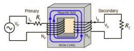
As the diagram (from http://hyperphysics.phy-astr.gsu.edu) to the left shows, the first coil is called the primary and the other coil is called the secondary.
The two coils are connected by a soft iron core, which channels the magnetic field from one coil to the other. The electrical power (P) is directly proportional to the current (I) and the voltage (V) and by conservation of energy, the energy produced by the primary is equal to the energy used by the secondary coil. The voltage in the coil depends on the number of turns in the coil and the change in the magnetic field (and area) in time. Since the change in magnetic field and the area are the same for both coils, the voltage is proportional to the number of turns (N). So
IpVp= Pp = Ps = IsVs
NpVp = NsVs
Vs = Vp(Ns/Np)
Note that as the voltage is increased on one side, the current must decrease. In addition, that if the current does not change, there is no induction effect. This means that an unchanging current (direct) is applied to the transformer, there will be no induced current in the other coil of the transformer.
Using alternating current on an electrical motor results in a motor that swings one way as the voltage is positive and then reverses as the voltage becomes negative. This can be ameliorated by the use of a rectifier or a commutator. A simple commutator is a mechanical device that only allows the motor to see the positive voltage. Hence, the motor will always turn in the same direction.
Activity 14-4: Simplest motor
Objective: Use the properties of a commutator to change an alternating current into a direct current to drive a motor
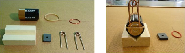
Materials:
• Two bare copper wire (16 gauge ~15 cm long) (in the class kit)
• Magnet wire 1.0 m (26 gauge enamel-covered copper wire) (in the class kit)
• Rectangular ceramic magnet (~2.5 cm x 1.5 cm) (in the class kit)
• Wooden base with groove (in the class kit)
• Rubber band
• Scalpel or knife (optional) OR steel wool
• 1.5-Volt cell
Procedure: Write your observations and answer questions for each of the following:
1. Using a pencil as a jig, wrap one piece of 16 g copper wire completely around it to form a loop with two long parallel legs. Repeat with the other piece. The legs should be even and about 1 cm apart.
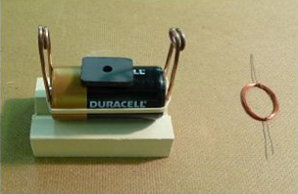
2. Wrap the 26 g wire in a coil with a diameter or 2 to 3 cm leaving about 5 cm free at each end. Use the free ends to secure the coil by wrapping them around the coil (in and out) several times.
3. Strip the enamel from one end completely for about 1 cm from one end. Strip the enamel from only ONE HALF of the other end for the same distance. An easy way to do this is to place the end on a table and scrape with a razor blade starting from inside out while holding the coil in one hand and scraping with the other hand. As you scrape, slowly turn the coil through 180°. The stripped copper wire has a bright copper color as opposed to the orange red enamel.
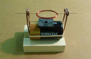
4. Place the 1.5 Volt D cell on the wooden base and wrap the rubber band around the 1.5 Volt D
cell.
5. Place the two 16-gauge copper wire loops at either end of the 1.5 Volt D cell.
University of Virginia Physics Department
6. Place the magnet on the top of 1.5 Volt D cell in the middle of the cell.
7. Place the coil of wire between the loops of the two clothespins so that the coil is directly over the magnet. Take care that the two ends (axles) of the coil are collinear with each other.
8. It may be necessary to nudge the coil to get the motor started, but it should run rapidly then. WARNING: the coil get hot with prolong use.
9. If the coil is not turning check the following:
a. The two free ends of the coil should be in a straight line with each other and there should be no sag in the coil.
b. The insulation may not be sufficiently stripped from one end or the other.
c. The 16 g copper loops may not be in contact with the terminals of the D cell.
10. (Store the coil separately so that the cell will not discharge and the coil will not melt). 11. Note that as a classroom activity, the components (except for the 1.5-volt D cell) cost less than a $1 per set up and can be purchased at the local electrical store or at an electronics store such as Radio Shack.
12. (Optional): The speed of rotation of the coil can be determined using a stroboscope. Or using a Vernire(™) voltage probe and LoggerPro(™), http://www.vernier.com/innovate/measuring-motor-speed/
13. Add the second magnet on top of the first magnet. Describe what happens to the speed of rotation of the coil. Provide an explanation for the change.
14. Make a second coil from magnet wire with a smaller diameter for the coil. Alternatively, rewind the original 1.0 m length around a smaller object. Describe what happens to the speed of rotation of the coil. Provide an explanation for the change. Careful: there are competing effects as both the area of the coil of magnet wire and the number of coils of magnet wire is changing. There is also another physical change in the coil as the moment of inertia changes with diameter of the coil.
15. Make a second coil from magnet wire with a length of 0.5 m. Alternatively, cut the original 1.0 m length and make a coil with half of the wire. Describe what happens to the speed of rotation of the coil. Provide an explanation for the change.
University of Virginia Physics Department