Home Lab 15 Diodes,
Transistors and Amplifiers Overview
by Thomas O’Neil for the University of Virginia Physics Department Reprinted with permission from T. O’Neil.
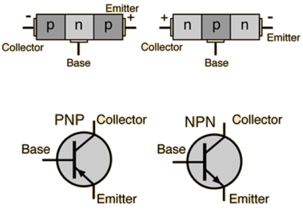
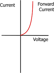
Diodes can be thought of as one-way streets. The electrical current may flow through the diode one way but not the other. The diode also requires a certain voltage (forward bias) in order to begin conducting. This turn-on voltage is depends on the main component of the diode. For a silicon diode, the turn-on voltage is approximately 0.6 volts while for germanium diodes, the turn-on voltage is lower, approximately 0.3 volts. The name, diode, arise from the fact that the silicon (or germanium) is doped with negative (N) materials which are sources of “extra” electrons and with positive (P0 materials which are sinks for electrons. A diode consists of a P type material next to an N type material.
Light emitting diodes (LEDs) are produced by changing the silicon or germanium for gallium arsenide. Silicon and germanium diodes typically only produce heat when a current flows through them. In this respect, silicon or germanium diodes are like weak one-way resistors. Gallium-arsenide diodes give off light through electroluminescence. The frequency and wavelength of the light emitted depend on the exact composition of the diode. Frequently overlooked, is the fact that LEDs will produce a current/voltage when light falls on the diode.
As the diagram (from http://hyperphysics.phy-astr.gsu.edu) below shows, two diodes placed back to (either NPN or PNP) form a simple version of a transistor.
A transistor is analogous to a valve. Current to the base controls the ability of current to pass through the collector-emitter path. If there is no current to the base, then there is no open path between the emitter- collector pair. Under these conditions, the transistor functions as a switch.
Finer control is available by changing the amount of current to the base. As the current to the base is increased, more current can flow across the collector-emitter. A small change to the base produces a large change across the collector-emitter. For a typical NPN transistor, this ratio can reach 200. That means that a 1 mA current to the base will allow 200 mA to flow across the collector-emitter. This is the basis of the simple transistor amplifier.
Activity 15-1: Diodes
Objective: Investigate the behavior of light emitting diodes.
Materials:
• Breadboard (in the class kit)
• Multimeter (in the class kit)
• 2x Red light emitting diode (in the class kit)
• Green light emitting diode (in the class kit)
• 1 000 (1k) ohm resistor (in the class kit)
• On/off switch (optional) (in the class kit)
• Connecting wires (jumpers) (in the class kit)
• 9-V battery snap connector (in the class kit)
• 9-Volt cell
• Short piece of plastic straw
Procedure: Write your observations and answer questions for each of the following:
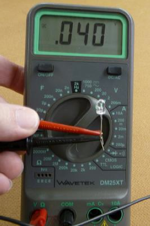
1. Set the multimeter to DC voltage and connects the leads to the legs of the red LED. The red (positive) lead should connect to the longer leg of the LED while the black (common, negative) lead should connect to the shorter leg of the LED. Turn the multimeter on and record the voltage in a well- lit room. Record the voltage. Provide a brief explanation for the voltage.
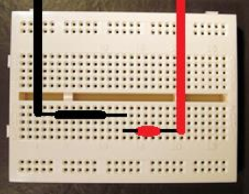
2. Place the 1 000-ohm resistor in the breadboard so that the resistor spans two columns of tie points. Connect the short leg of a second red LED to one end of the resistor. Plug the long leg of the second red LED into the breadboard in a third column of tie points. Connect the 9-Volt battery so that the positive (red) lead connects to the long leg of the Led and the negative (black) lead connects to the far end of the resistor.
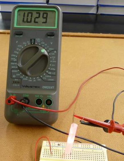
3. Place a short piece of straw (any large fast food straw will do. Hint: try a McStraw) over the lit red LED to act as a light shield.
4. Take the first LED that is connected to the voltmeter and invert it into the open end of the straw. Record the voltage. Provide a brief explanation for the voltage.
5. Replace the breadboard LED with a green LED.
Replace the straw light shield and invert the red LED, which is attached to the voltmeter into the open end of the straw. Record the voltage. Provide a brief explanation for the voltage.
6. Replace the breadboard LED with a red LED. Replace the red LED attached to the voltmeter with the green LED. Ensure that the red (positive) lead of the voltmeter is connected to the long leg of the green LED and the black (common, negative) lead of the voltmeter is connected to the short leg of the green LED. Replace the straw light shield and invert the green LED, which is attached to the voltmeter into the open end of the straw. Record the voltage. Provide a brief explanation for the voltage. Provide a brief explanation for why both a red LED and a green LED cause a significant voltage in the red LED but a red LED does NOT cause a significant voltage in the green LED.
University of Virginia Physics Department