 |
||||||||
|
Intro to Circuits
PH.13 The student will investigate and understand how to diagram and construct basic electrical circuits and explain the function of various circuit components. Key concepts include a) Ohm’s law; b)
series,
parallel, and combined circuits; and circuit components
including resistors, batteries, generators, fuses, switches, and capacitors. National Standards:
Circuits and Ohms Law Topic/Concept Circuits and resistance Materials per group
Safety Considerations Students will burn themselves if they short out a
battery with a wire. Presentation I use this as a conceptual introduction to the topic
of circuits. I begin by introducing some vocabulary and then they student have
about 80 minutes to do the activity. After the activity we convene as a class
and go over the answers. The activity becomes their notes. Teacher Tips Regarding Lab Holiday
lights that go on a 100-count string that plugs into a wall outlet are rated at
2.5 volts. Holiday lights that go on a 20-count string that plugs into a wall
outlet are rated at 6.0 volts. This gives you 2 sets of bulbs with various
resistances.
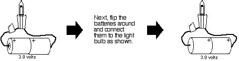
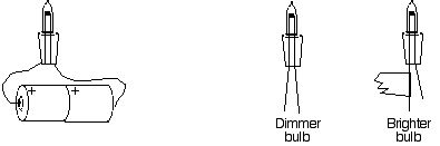
Parallel & Series Circuit Notes/Activities Answer questions in complete sentences, when possible. Sort your light bulbs according to brightness. To do this connect the ends of each bulb to a pair of batteries. Attach a piece of tape to one of the wires on each BRIGHT bulb.
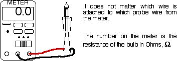
Take the brighter and dimmer light bulbs to the “Ohm Meter” in the room. Attach the leads of the meter to the ends of the wire on the light bulb.
1 Resistance of the “dimmer” bulbs:
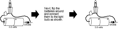
Attach a “Zenor” diode to one of the ends of the light bulb. The zenor diode is a small black cylinder on a wire. It has a thin silver band around the circumference at one end. It does not matter which end the diode is attached to or which side of the diode faces the light bulb. Repeat the steps above.
4 What function does the diode perform to the current flow?
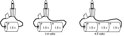
Take the brighter light bulbs and keep adding batteries until the bulb burns out. Combine your resources with another group. Burn out ONLY one light bulb. Put an “X” on the burnt out bulb’s tape.
6 Describe what you see happening to the light bulb as more and more batteries are added.
7 How many volts did it take to burn out the light bulb?
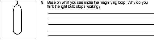
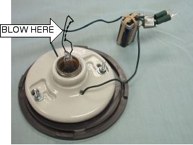
Elsewhere in the classroom is a burnt out light bulb, it is under a 30X magnifying loop. Take a look at and draw what you see inside the bulb.
9 A light bulb is really a resistor that glows. Draw a box around the schematic symbol that stands for the light bulb in your circuit.
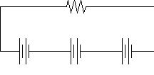
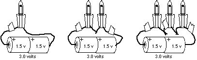
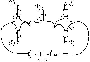
10. The batteries are connected in series and light bulbs are all connected in series. Draw a circuit for each diagram above in the space below.
12. The brightness in each light bulb is directly proportional to the voltage delivered to the light bulb -because each bulb has the same resistance. Explain why each light bulbs’ brightness is affected the way it is was when they were added in SERIES in terms of what we have recently studied in electricity.
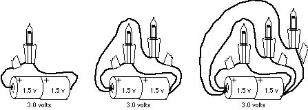
14. What is the effect on the bulbs’ brightness when the extra 2 pieces of wire are added?
15 The brightness in each light bulb is directly proportional to the voltage delivered to the light bulb -because each bulb has the same resistance. Explain why each light bulbs’ brightness is affected the way it is was when they were added in PARALLEL in terms of what we have recently studied in electricity.
16 In the space below, draw the circuit for the picture.
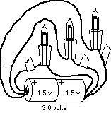
17 What is the effect of making the length of wire between the batteries and the light bulbs longer?
19. What is the effect of running two simultaneous sets of wires, Circuit [ C ], between the batteries and the light bulbs?
23. How do you think the lights and outlets are wired in your home. Are they in series or parallel? Explain your answer.
25 Hold your arm about 8 inches from your mouth. Blow on your arm. What do you feel happening to the temperature of your arm when you blow on it?
26 Look for the setup shown below in the room. The thin wire in the center of the fixture is a light bulb filament. (IT IS VERY FRAGILE. Do NOT touch it. It WILL break if you touch it.) GENTLY blow on the thin wire in the center of the firxture. While blowing, observe what happens to the light bulbs’ brightness.
26 Based on your observations, explain what you think happens to a wire’s resistance as it is cooled.
|
 |
A special thanks to VASTfor hosting our web site. |
|
 (2) Resistance of the “brighter” bulbs: