 |
||||||||
http://vip.vast.org Hi everyone, Hope you have survived the 3rd 9-weeks and a pretty wild winter. Spring is finally here and we are looking forward to our annual VIP spring meeting at UVA later this month. It is coming fast! Hope to see everyone on April 26. In this issue we have:
I always look forward to taking the time to connect with great teachers from across the state. I hope you make up to spend the day with us at the VIP Spring meeting. Until then, Timothy Couillard President, Virginia Instructors of Physics (VIP)
Who: Physical Science, Physics teachers, and University physicists. When: April 26th (time agenda below) 8:30 AM – 3:00 PM Where: Department of Physics Jesse Beams Laboratory, University of Virginia There is a good web map at http://www.virginia.edu/webmap/GMcCormickRoadArea.html The physics building is #41. You may want to park behind #38 off of stadium road. Do not park at the physics building. This is 24/7 permit parking. Cost: Free!!! RSVP IF ATTENDING
Modeling Instruction at the 2014 James Madison University CTA Thanks to support from the Virginia Department of Education, James Madison University, and school divisions statewide, Modeling Instruction Training for Physics, Chemistry, Biology, and Physical Science will return to the JMU Content Teaching Academy in 2014. This year both Introductory and Advanced academies will be offered. The program was recently featured in state and local media: http://goo.gl/OOyBlf Contact Joe Mahler for additional information at joe.m.mahler@gmail.com.
©Modeling Workshop Project 2009 For more Modeling Instruction curriculum materials, visit http://modelinginstruction.org/ to find a Modeling Instruction Workshop near you. PurposeUpon completion of this activity students should:
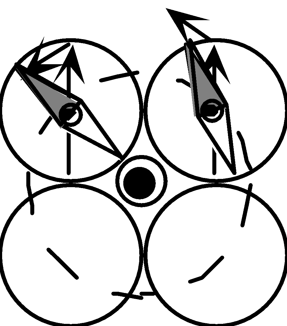
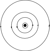
ApparatusPower supply Resistor or rheostat Wire Compass Ringstand Cardstock Pre-lab discussionPre-lab discussion should begin with a demonstration that a small compass will show a deflection when current runs through the wire. Using “top” and “bottom” sticky tapes and a simple circuit it can be shown that the compass is responding to a new field, distinct from the electric field. This conclusion arises from the observation that: The compass can be introduced as a “test” for the presence of a magnetic field. The direction of the force on the north end of the compass is (arbitrarily) chosen to represent the direction of the magnetic field. Charge students with the task of exploring this new field in the vicinity of a current-carrying wire. What does it look like? What happens when the direction of the current is reversed? Qualitatively, what happens to the strength of the field as you move away from the wire? Performance notes The setup for the lab is a circuit that contains a length of wire that passes vertically through a piece of cardstock. The lab data sheet suggests positions to place the compass to determine the “look” of the field around the wire, when current is flowing in each direction. The magnetic field produced by the current will cause the needle to deflect from North. The direction of the force is the direction of the North end of the compass’ deviation from North. Careful observation will show that the deflection of the needle is somewhat greater in the NW and SW positions than in the NE and SE positions when the current is directed upwards. Students should also note that the compass deflection increases as the current increases. In the post-lab discussion, help students to recognize that the final needle position is due to the superposition of the Earth’s magnetic field and field produced by the current. Have students represent their findings on whiteboards. Consider a roundtable discussion to elicit the main points of the lab; moving charge creates the magnetic field, the field lines form closed loops, and the field weakens as you move away from the source. Because the direction of the field at a given point in space is defined as the direction of the force on the North end of the compass, the right hand “curl rule” should fall out as a natural consequence: when the thumb of your right hand points in the direction of positive charge flow, the fingers of that hand naturally curl in the direction of the field. Thus the picture of the field that is eventually settled upon should look like this (in the case of charge flow toward the viewer): Introduce the convention of dots to represent a field or current directed toward the viewer, and crosses for quantities directed away from the viewer. Measuring the magnetic field due to current in a wirePurpose-Part 1The purpose of this experiment is to determine the relationship of the strength of the magnetic field around a current carrying wire and the distance of the field from the center of the wire. The current is held constant.
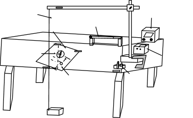
Apparatus Power supply, a compass with degrees marked around the circumference (preferably marked under the tip of the needle), a ruler, sheet of paper, wire, multimeter or ammeter (5 or 10 amp), rheostat (depending on power supply), switch, clamps, aluminum rods, tape, book ProcedureNote: it is very important that this lab be done on a surface that has no current running underneath it, and no ferrous metal (chairs, steel legs, bolts, etc.) near or in it. On some lab tables it is necessary to add an extension to the table and place the compass and paper on it to get away from ferrous materials.
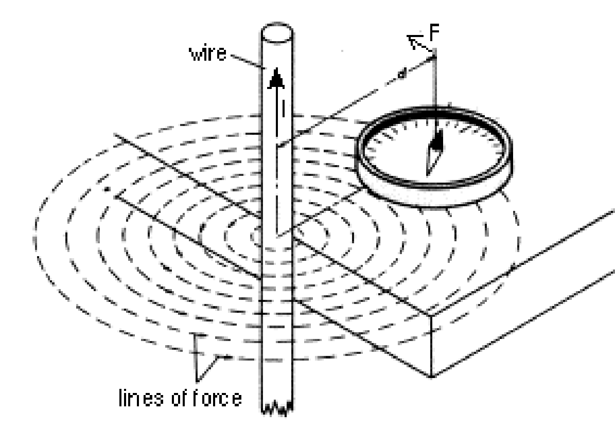
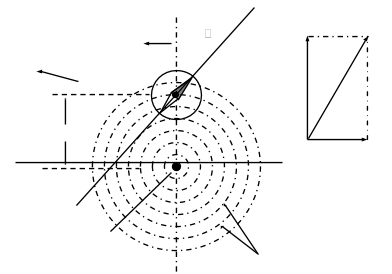
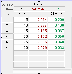
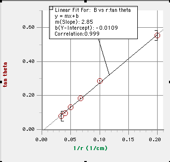
Background and Magnetic Field TheoryN-S line of the earth’s magnetic field d Wire Field lines Table The magnetic field due to a wire encircles the wire as shown in the diagram to the right. The equipment is set up with the compass placed along the north-south line of the earth’s magnetic field. Since the magnetic field around the wire is circular, if the compass is placed along the N-S line, then the earth’s field and that of the wire will be perpendicular to each other. The result will be a deflection of the compass needle somewhere between the N-S line of the earth’s magnetic field and the E-W line of the current carrying wire’s magnetic field, along the resultant of the two magnetic fields. The deflection of the compass needle obviously depends on the relative strength of the magnetic field of the current carrying wire’s compared to that of the earth at the same location. In the diagram above right, represents the magnetic field vector from the wire and represents the magnetic field vector of the earth. Since the strength of the Earth’s magnetic field remains constant during the experiment, we can say that . A plot of tan vs r will allow students to determine the relationship between the strength of the field and the distance from the wire. Evaluation of dataBelow is a sample data table for the lab and the modified graph produced from the data..
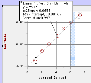
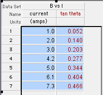
Since the actual value of the magnetic field strength was not determined, but is proportional to tan , students should be able to conclude that the strength of a magnetic field produced by charges moving in a wire is inversely proportional to the distance from the wire. Purpose- Part 2The purpose of this experiment is to determine the relationship of the strength of the magnetic field around a current carrying wire and the amount of current through the wire. The distance from the wire is held constant. ProcedureThis experiment uses the same apparatus and techniques as part 1. The difference is that the distance from the wire is kept constant at a value from 5 and 10 cm and the current in the wire is varied from 0 to 5 amperes.(More current works well but your power supply must be able to provide it.) Students will use their data to determine the relationship between the magnetic field around the wire and the current in the wire. Evaluation of dataBelow is a sample data table for the lab and the graph produced from the data collected when the compass was placed 5.0 cm from the wire. Using the argument cited in part 1, students should be able to conclude that the magnetic field strength is proportional to the current in the wire. With some encouragement, they should also be able to combine the proportionalities to state that for the magnetic field produced by current in a straight wire. For quantitative problems, the constant of proportionality is , so the relationship is
http://advancesinap.collegeboard.org/math-and-science/physics
The Big Ideas
Science Practices
Opportunities for Physics Teachers
Need funding for an innovative curriculum activity? VAST's minigrant application for funding is due June 1. The application is short and can be found here:
http://www.vast.org/grants.html
AAPT Summer Meeting: Minneapolis, MN July 26-30 2014 http://www.aapt.org/Conferences/sm2014/James Madison Content Teaching Academy, June 23-27 Matter and Interactions Distance Education Course http://www.matterandinteractions.org/Content/HSteachers/teachers.html Modeling Instruction Summer Workshops http://modelinginstruction.org/information-on-summer-2014-workshops/ NSTA 2014 Area Conference: Richmond Virginia October 16-18 http://www.nsta.org/conferences/ "Science of Nuclear Energy & Radiation" 2014 4-DAY Science Teacher Workshop, http://local.ans.org/virginia/public_education.html UVA Professional Development Opportunities in Physics Education http://k12.phys.virginia.edu/home.html Virginia Association of Science Teachers Profession Development Institute (VAST-PDI) November 19-22, 2014 at the Hotel Roanoke. http://www.vast.org/annual-pdi.html Woodbury School’s 2014 Open Lab Summer Institute, July 27-29 http://jacobsphysics.blogspot.com/2014/02/open-lab-2014-july-27-29-at-woodberry.html
VIP website:Visit the Virginia Instructors of Physics website at http://vip.vast.org/ Are you on the email list?
If you have any physics-related questions, news, or anything else? Please post it to the yahoogroup (http://groups.yahoo.com/group/va-inst-phys/) or send it to us directly. Contact Info President: Timothy Couillard (@coolyrd), timothy_couillard@ccpsnet.net Vice-President: Jeff Steele, jeffsteele1@gmail.com Webmaster: Tony Wayne, twayne@k12albemarle.org SupportThis newsletter and our spring meeting are graciously hosted by the Physics Department of the University of Virginia. The Make&Take session is funded by the Virginia Association of Science Teachers (VAST) of whom we are an affiliate and Jefferson National Laboratory. Spring meeting door prizes generously donated by Vernier, CPO, Sargent-Welch, Frey, Arbor Scientific. Thank you for all you do to promote physics education in Virginia and beyond!
VIP is an affiliate of the Virginia Association of Science Teachers (VAST), vip.vast.org |
 |
A special thanks to VASTfor hosting our web site. |
|